
Field Coil Speakers
The history of speakers commenced in 1874, when the German engineer Ernst Werner von Siemens, founder of Siemens, described the design featuring a circular T-shaped coil positioned within a magnetic field. The vertical movement of the voice coil became feasible thanks to a specialized mount. Ernst von Siemens highlighted the device’s potential for audio playback. Subsequently, Siemens filed two patents that essentially outlined the loudspeaker design. Following numerous refinements around the 1920s, dynamic cone speakers evolved into a type that has seen little alteration to this day.
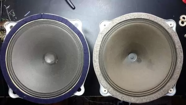
The majority of speakers produced before World War II featured what’s known as a field winding coil or field coil. As powerful permanent magnets with stable properties weren’t yet developed at that time, it was much cheaper and more effective to utilize solenoids. These solenoids, or T coils/field coils, were mounted within the magnetic system and connected to a constant voltage source. Speakers utilizing field coils continued to be manufactured in the 1930s, 40s, and even the 50s. Renowned firms such as Klangfilm, Siemens, Telefunken, Western Electric, and SAR produced speakers with solenoids, which were considered unsurpassed in accentuation and sound expressiveness, often fetching high prices at auctions.
While field coils may seem antiquated today, there has been a steady resurgence of interest in such speaker designs worldwide. Individual enthusiasts and even companies are producing speakers utilizing magnetization or modifying electromechanical speakers from other manufacturers.
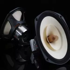
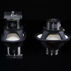
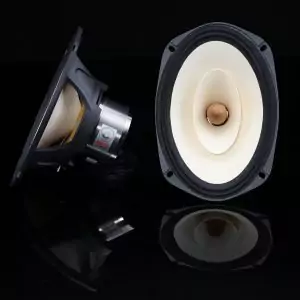
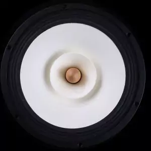


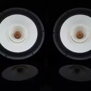
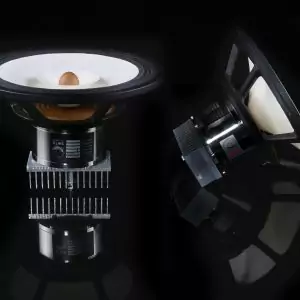
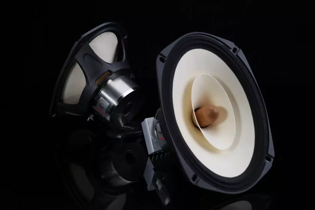
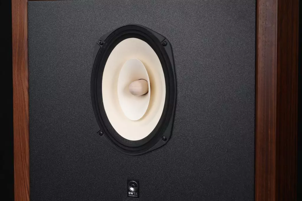
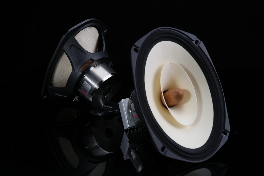
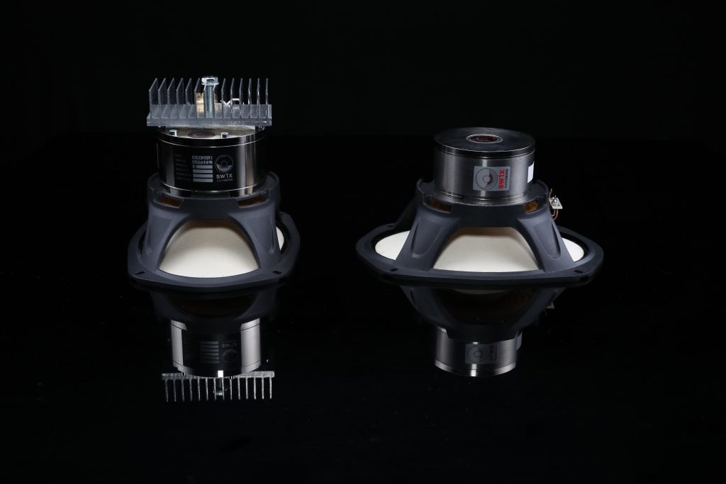
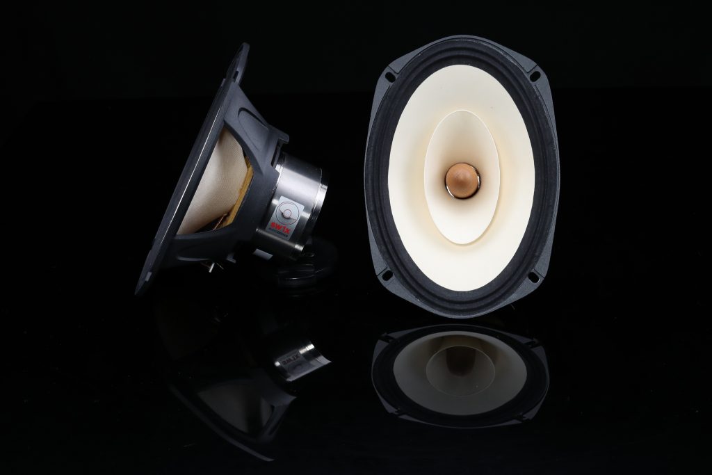
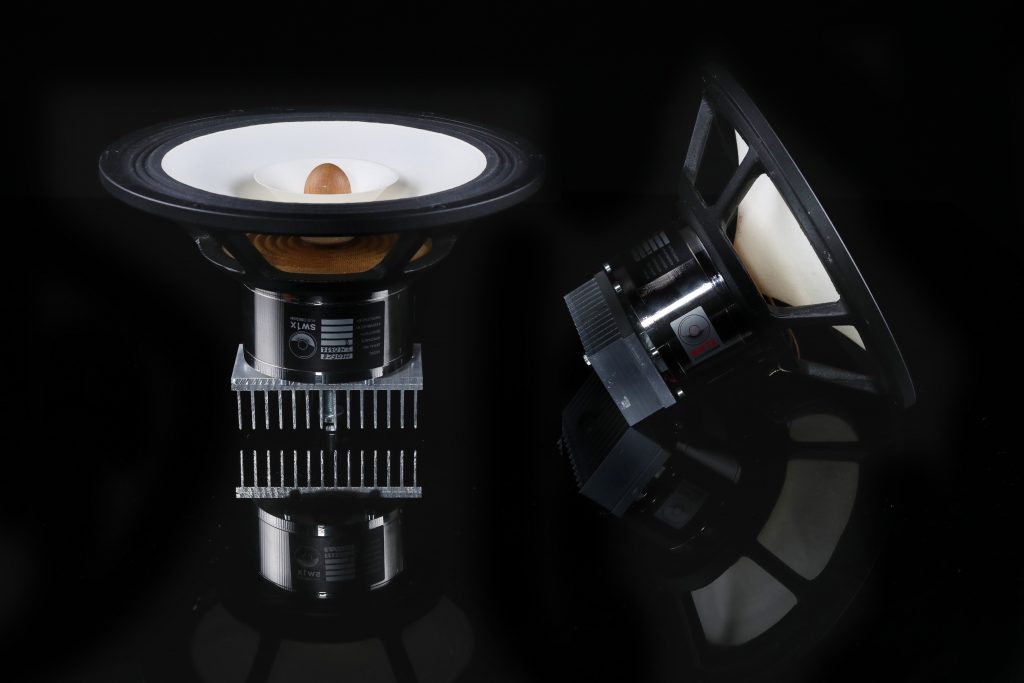
SW1X Audio Design Field Coil Drivers
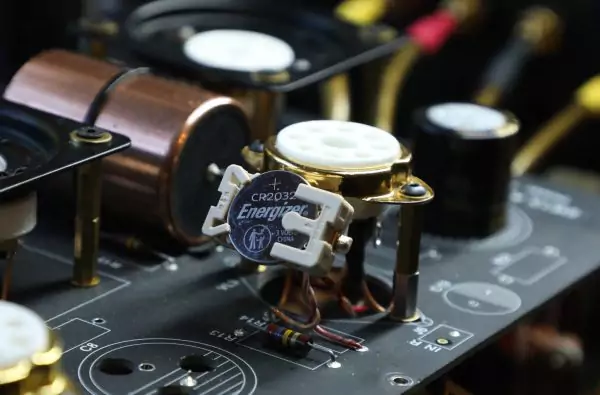
Whether there’s a rational basis for these endeavours or if it’s simply a trend in audio technology remains a question. One advantage of field coils is their ability to adjust the magnetic field tension within the dynamics of the T coil, allowing for fine-tuning of speaker tone balance and bass playback quality. Electromechanical speakers lack this capability. However, field coils are less convenient in other aspects; poor filtration of pulsations from the bias can lead to audible AC interference. Additionally, the quality of materials used in the construction of the magnetic body and the T coil is crucial for speaker sound. Factors such as wire painting and transparency, as well as the components of the power supply for the field winding coil, significantly influence sound quality. These considerations, while not fully explained by modern physics, are vital in audio engineering. Through experimentation with field coil, I have assembled several dozen power supply units for various speakers.
The starting point for my experiments has been the recommendations of Anatoly Markovic Likhntsky, a renowned engineer and author of several conceptual articles on audio:
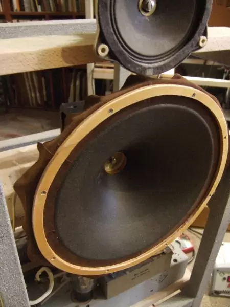
Anatoly Markovic began using bias speakers in the early 1960s, and now, in a mono speaker setup, the main range is played by a 15-inch woofer, Klangfilm 44022, biased, while above 5 kHz, a 4-inch field coil preforming Siemens, released in 1938, is utilized.
As Anatoly Markovic’s texts on bias speakers are challenging to find online (as they are posted in a closed forum and not indexed by search engines), I’ll share a few excerpts from his communications saved on my computer:
“The power source for magnetized speakers is crucial! It’s often overlooked that power sources for engines and seemingly unrelated electrical components affect sound quality over a relatively long distance. Although this was understood to some extent, the full extent hadn’t been explored until recently. Anton Stepichev recently drew my attention to the power source for field winding coils. Since I was primarily focused on carpentry, I initially missed Anton’s point and connected the Klang and Siemens speakers directly to the network via a diode bridge CC405 and parallel Tesla 300 690091 capacitor. The sound was remarkable initially, and questions about the power source weren’t raised. However, the diode bridge failed during operation. Upon replacing it, I decided to use a kenotron rectifier with a power transformer and U-filter. I used old Soviet elements, hoping their impact wouldn’t be significant. Yet, upon the first power-up, the sound was vulgar and distorted. It felt like previously assembled components were from different eras, not communicating effectively. Listening to music was impossible. I then realized that even after the power source was disconnected, there was residual magnetization affecting sound, albeit subtly. This realization allowed for a focused assessment of the power source for field winding coils as a benchmark for comparison. Further adjustments were made: full-wave rectification was replaced by half-wave, resulting in cleaner sound; the electrolyte in the filter was changed several times, settling on “inform us Gate” brand; old Soviet lines were replaced with Telekovsky, oriented correctly according to Anton Stepichev. The choice of kenotrons (5u3) was narrowed down to Soviet, Sylvania, and Samsung, with Soviet ones being preferred despite their lack of finesse due to their sharpness and clarity. Ultimately, I reverted to a transformerless setup through a semiconductor diode bridge, with a small Telekov wire coil preceding the electrolyte to prevent bridge failure. This approach yielded the best sound quality, demonstrating that experiments with wires, kenotrons, transformers, and chokes are crucial for the power supply of field winding coils. Firstly, it ensures the safety of the sound path; secondly, it enhances sensitivity to component replacements and harness direction changes, comparable to the output stage of a powerhouse; and thirdly, it maintains standard sound quality even with bias disabled.“
……………………………………………………………………….
“I was captivated and continued my experiments with magnetization. Instead of a silicon diode, I opted for a germanium junction. After rummaging through several bottles, I couldn’t find a germanium diode, but I stumbled upon an old Soviet cuprox rectifier. I replaced the silicon diode with it and immediately noticed changes in the sound. I wouldn’t say the sound improved, but it was different; in any case, the toxicity of silicon was clearly absent. There was a significant increase in sensitivity to even the slightest installation changes. For example, I have two types of solder: Telekovsky and Old French (donated by Dphsc Stechiv). So, when I solder with the French soldering iron, I immediately hear a softening of the sound and a loss of highs, and if I switch to Telekovsky, I immediately feel increased dryness. I fused the two solders and achieved the desired balance, but I found a mild note present in the RF that separated from the tweeter of the noblest Klangfilm.
In the final step, I inserted 5 cm of Antonov’s wire into the rectifier, which he himself considers the best. The miracle happened—the tweeter speaker seamlessly merged with the noble wave of the Klangfilm, eliminating any signs of sovietness. This smoother listening impression inspired me, echoing what I previously expressed in the article about the Medvedev amplifier. Some of the most highly organized conductors are beginning to influence less organized elements and conductors such as domestic production. Furthermore, they capture power from the power source and declare themselves enlightened dictators. This social behavior isn’t limited to conductors; even electrons, as predicted by Tesla, exhibit similar tendencies. This was discussed in a recent episode of “Russia” dedicated to Tesla.“
With respect, Anatoly Likhnitsky
“Finally, I realized a single-ended transformerless power source for Klangfilm, upgrading to an Ebee kenotron RGN 4004 and compared it with a transformerless bridge rectifier. The diode provides clearer sound, but there’s some rigidity or rudeness in the tutium field, whereas the kenotron stiffener offers less clarity but no such rigidity. The brightness heavily depends on all conductors of the source and increases when the network is as straight as possible into the kenotron and further to the coil of the bias of the speaker.“
With respect, Anatoly Likhnitsky
“I decided to compare the RGN 4004 with an ordinary silicon cell diode in the bias. The result was expected. Firstly, the diode has a directional effect, not just in terms of continuity but also in its impact on the sound. In the schematic field winding, it can be reversed and verified that in one of its directions, the sound is less treated than in the other.
When compared with the kenotron sound, the diode is more aggressive, albeit more articulate. However, the human voice seems to disappear, and listening to music for an extended period becomes less desirable. These experiences are akin to those observed in the transition from direct playback of Uzbek music culture to its optional playback via al-Yes. While I can only speculate (due to insufficient data), it seems that silicon as a material, unlike the decorated structure of al-Yes, creates a heightened sense of recording. Therefore, one can expect a significantly better sound only when using a microtube al-DA converter.“
With respect, Anatoly Likhnitsky
……………………………………………………………………….
“In addressing the issue, I made a simultaneous decision on several fronts. I connected the coil magnetizer of Klang and RF Siemens speakers in series. As a result, the sensitivity of the tweeter speaker did not meet expectations. It was necessary to increase the voltage at the RF coil-speaker. Two options presented themselves:
- Shunting the Klang coil with a resistor.
- Creating an independent bias source for the tweeter speaker.
My final version :
Transformerless coil power field winding speaker Klangfilm
The nominal voltage is 250 IN/ current 60 mA. In connection with the fact that I have reduced the resonance frequency of the mobile system Klang, I picked up the same open box to listen to the optimum supply voltage bias of 200 V. I straightened the network half-wave via one anode of the kenotron RGN4004. There is no throttle – only the capacitor 5 µf from old firm Bosch (paper-oil)(бумагомаслянный), which is parallel to the Field Winding Coil.
The tweeter from Siemens is 10 cm (Высокочастотник firm Siemens 10 cm)
It is powered from the half-wave rectifier on a germanium diode CC (1952 release), parallel to the field winding coil with an enabled electrolytic capacitor from this firm, 1000 690091\100 In (1950 release). To set the correct voltage, I used a buck transformer from firm B&K (1950 release). The selection of voltage shifting the coils was completed by listening.“
With respect,
Anatoly Likhnitsky
Follow us on Facebook, Instagram, YouTube and Pinterest. Join the official SW1X Audio Club